Fiorini P, Linnane G, Keily M, Coyne J, Grygorczuk M, “Large-Volume Injectors: Rise in Biologics Brings Challenges”, ONdrugDelivery, Issue 105 (Feb 2020), pp 47-50
Developing devices capable of delivering highly viscous biologic drug formulations at high volumes does not come without its challenges. Paolo Fiorini, Gerard Linnane, Michael Kiely, Maciej Grygorczuk and Joshua Coyne discuss these challenges and the merits of various drive solutions.
“One of the primary challenges in developing LVIs is the large injection forces required.”
It is anticipated that the market size for large-volume injectors (LVIs) will be US$8.1 billion (£6.2 billion) by 2025.1 This demand is largely being driven by growth in the biologics sector – one-third of annual drug approvals are now in biologics.2 Typically, these drugs are highly viscous and require large-volume injections to achieve the required therapeutic dose.
Capability for the patient to deliver these drugs at home using an autoinjector would bring many advantages. There is a huge psychological benefit to the patient in administering their medication at home, in an environment that is comfortable and familiar to them, leading to improved patient outcomes. This also lessens the burden on the health system through reduced hospital visits and outpatient procedures.3
WHY SO CHALLENGING?
One of the primary challenges in developing LVIs is the large injection forces required. Some of the main factors that impact the injection force are:
- Drug viscosity
- Drug volume
- Injection time
- Syringe barrel internal diameter
- Needle internal diameter
- Needle length
- Friction forces (including stiction).
These relate to the required injection force (Finj), as modelled by the Hagen-Poisseuile equation, for non-Newtonian fluids (Figure 1).
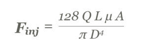
Figure 1: The Hagen-Poisseuile equation for non-Newtonian fluids.
For example, moving from a low viscosity 1 mL injection to a high-viscosity 5 mL injection will first require an increase in the flow rate (Q) to maintain a similar injection time. The viscosity value (μ) will increase with increased viscosity formulations. Furthermore, barrel diameter (A) can be increased to maintain the overall length of the device. The needle characteristics of length (L) and inner diameter (D) will typically stay the same so as not to adversely impact patient comfort. All these changes will contribute to a significantly higher injection force (Figure 2).
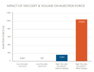
Figure 2: The impact of viscosity and volume on injection force.
NON-NEWTONIAN FLUIDS
“The four most common solutions are spring drives, gas drives, electromechanical drives and chemical drives.”
Another factor to consider when assessing the interaction between the drug and the device are shear rates. Many biologics behave in a non-Newtonian manner and do not adhere to the standard Hagen-Poisseuile model. Commonly, they exhibit shear-thinning properties such that their viscosity during injection reduces for increased flow rates – corresponding to a lower injection force than predicted in the standard model.
Each drug formulation should undertake a rheological assessment to understand its behaviour during injection. This would avoid potential over-engineering of the device to provide an injection force that is above requirements. From a drug viability perspective, it is important to understand the impact of high shear rates during injection on drug integrity and performance – for example, to avoid damage to the drug.4
WHAT ARE THE OPTIONS?
Having established the need for a high force to drive the injection, what are the main options out there to achieve this? The four most common solutions are spring drives, gas drives, electromechanical drives and chemical drives. Here, a brief overview of each option is provided along with benefits and challenges of each.
Spring Drive
The most widely used energy source for autoinjectors is the spring drive (Table 1). This solution has many advantages, with a wide selection of established suppliers to the medical device industry, well understood automated assembly methods and a relatively low cost. However, the high force required for LVIs introduces several challenges for spring mechanism designs.
| Benefits | Challenges |
| Lower cost solution | High load during storage |
| Non-complex assembly | Variable injection speed |
| Low risk for drug compatibility issues | Device size |
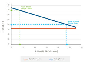
Figure 3: Injection versus spring force.
Table 1: Spring drive benefits and challenges.
Typically, the spring driven mechanism will need to be stored in a compressed state for a long period (more than three years). The force in this compressed state is driven by the maximum injection force, along with the force required to compress the spring to its starting position (Figure 3).
It will be necessary for the components used to maintain the spring in a compressed state to be highly resistant to creep. A cost-effective solution here would be to use high-performance polymers such as liquid crystal polymer. However, it would require extensive finite element analysis and materials testing to understand the material performance over the required storage time.
A potentially more expensive but lower-risk solution would be the use of metallic components. For these, careful consideration should be given to the optimal manufacturing method at an early design stage. For a pen injector device, deep drawing and impact extrusion can be cost-effective methods for producing metallic parts with hollow, cylindrical geometries. Part geometry should be optimised at an early stage to suit the chosen manufacturing method.
An additional challenge with spring-driven mechanisms is maintaining the overall length within an optimal form factor for usability. For a standard compression spring, there is a minimum compressed length that can be achieved based on the maximum force required, the length of travel required and the k-factor of the spring. This could potentially be reduced by using novel spring designs such as volute springs – a conical spring with a short, compressed length – or dual springs. Clock springs could also be used in this application, which would give the added benefit of maintaining a constant force over the injection travel.
Gas Drive
Compressed gas has many advantages as a drive mechanism (Table 2). It can generate a very high force output within a small form factor. It requires very few components to operate and exhibits low noise during operation.
| Benefits | Challenges |
| High power density, only applying force when actuated | Gas sensitive to pressure and temperature |
| Can provide a constant pressure | Leakage and exhaust gas management |
| Quiet during use | Limited supply chain options |
Table 2: Gas drive benefits and challenges.
However, selecting the appropriate gas for the application can be challenging. Principally, there are two main options – single-phase gases and dual-phase gases (including refrigerants). As refrigerant gases are typically being phased out due to their environmental impact, single- and dual-phase gas options excluding refrigerants are discussed here. Two of the more challenging aspects of a gas drive design are discussed in further detail here – pressure output stability and leakage.
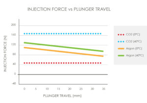
Figure 4: Injection force versus plunger travel.
Single-phase gases will have a reduction in pressure output from beginning to end of delivery and exhibit a relatively low sensitivity to temperature. Dual-phase gases will provide a relatively constant pressure over the drug delivery; however, the pressure output is highly sensitive to ambient temperature (Figure 4). Understanding operational temperature range, required injection time and expected injection force profile are critical in selecting the correct gas solution for the application.
It is also important to consider leakage from the container over the device lifetime. What detections should be put in place at production to mitigate against leaking canisters? – i.e. weighing the gas contents at various stages through production, adding tracer elements to the gas for detection or temperature testing to raise the internal pressure of the gas and stress test the canisters. Isolation of the gas from the drug and venting of the gas are other design features that it is critical to assess and implement into the design.
Electromechanical Drive
For a platform injector device, an electromechanical drive mechanism (Table 3) can provide the flexibility and tunability required to deliver a range of drug viscosities and volumes with customised drug delivery profiles. It also has the advantage of adding connectivity to help with patient monitoring and compliance. There are, however, some challenges for electromechanical drives.
| Benefits | Challenges |
| Hugh flexibility as a platform device | Potentially high cost solution |
| Potential to add connectivity | Meeting power requirements |
| Low risk for drug compatibility | Firmware development |
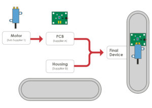
Figure 5: PCB assembly.
Table 3: Electromechanical drive benefits and challenges.
Integration of the electronics and the componentry into the overall mechanical design is a significant challenge. This requires a strong systems-level engineering approach to ensure a robust device at production volumes. Here are some examples (Figure 5) where a motor and printed circuit board assembly (PCBA) must be assembled into the plastic bottom housing of an injector pen. The motor has negative and positive terminals on its undercarriage that are to align with contact pads on the PCBA. This contact will require an interference fit to ensure a robust electrical connection. Both the PCBA and the motor will be heat staked into position using posts in the bottom housing.
For a successful assembly, it is critical to understand the PCBA requirements – namely, the manufacturing tolerances, the cut-out tolerances and the component placement tolerances. Assembly tolerances for placing the PCBA and the motor into the housing are also important. Finally, the moulding tolerances on the plastic housing need to be considered. In a typical project, components will be sourced from multiple suppliers (Figure 5). Systems-level planning and execution are critical to ensure the final device will assemble correctly and function as intended when these components are brought together in the final device.
By adding electronics to the device, there is also additional complexity in testing that will need to be completed on the device to meet stringent electrical safety standards. The firmware development will also need to be managed in conjunction with the PCBA design and validated to ensure it meets requirements.
Chemical Drive
Using the energy created from a chemical reaction can be a novel approach to generating the required injection force for an LVI (Table 4). Some of the advantages to this method include the high energy density achievable in a compact size and the potential to control the reaction to meet your requirements – i.e. a lower initial force to mitigate against high impact on the drug container. However, there are some challenges to this method that will need to be overcome.
| Benefits | Challenges |
| Very high potential power density | Force profiles susceptible to environmental challenges |
| Low number of moving parts | Environmental disposal challenges |
| No stress / pressure in stored state | Development time (novel technology) |
Table 4: Chemical drive benefits and challenges.
When one considers the use of chemical energy, the risk that frequently comes to mind is an out-of-control reaction. This is a very real issue but there are many ways to use the energy from a chemical reaction in a controlled, safe and regulated manner.
One such possibility is the use of an electric source to stimulate and thus regulate the chemical reaction through electrochemical interactions. This gives greater flexibility to the designer in creating a delivery profile that matches the device requirements. With the addition of a PCBA, programmable delivery profiles can be created to offer greater flexibility as a platform device.
Other possibilities include mechanical pressure release valves to regulate the progression of pressure build-up or bypass mechanisms that attenuate the reaction once it has progressed outside of the desired parameters. This occurs either through the release of a regulator or through reduction of an active component in the reaction.
A major factor that must be accounted for in the control of chemically driven devices is sensitivity to the environment, particularly temperature, which will directly impact the reaction. Any successful control mechanism must adequately account for this. Other factors for consideration include isolation of the chemical element from any contact with the drug container or the drug itself and understanding the variation of the force output within the operational conditions of the device.
CONCLUSIONS
Developing a handheld injector to deliver large volumes (>1 mL) of highly viscous drugs in a short time period (<30 s) poses some challenges. The main consideration is generating the high injection forces required. Discussed above are some of the potential options to generate the required force using either spring, gas, electromechanical or chemically driven mechanisms. There are benefits and challenges for each mechanism that should be assessed against the specific device requirements.
REFERENCES
- “Bolus Injectors Market, 2014-2024”. Research Report, Roots Analysis, Nov 2013.
- “Medicines in development for Biologics 2013 Report”. Research Report, PhRMA, April 8, 2013.
- Leff B et al, “Hospital at Home: Feasibility and Outcomes of a Program to Provide Hospital-Level Care at Home for Acutely Ill Older Patients”. Ann Intern Med, 2005, Vol 143(11), pp 798–808.
- Dreckmann T et al, “Low volume aseptic filling: Impact of pump systems on shear stress”. Eur J Pharm Biopharm, 2020, Vol 147, pp 10–18.
Previous article
ADDRESSING THE EVOLVING NEEDS OF VARIABLE DRUG DELIVERY REGIMENSNext article
DEVELOPMENT OF A NEW HIGH-PERFORMANCE AUTOINJECTOR
