
Citation: Delcroix I, “Assessing the Impact on Drug Dose Delivery of a Two-Step Autoinjector”. ONdrugDelivery Magazine, Issue 67 (May 2016), pp 38-42.
Isabelle Delcroix introduces a two-step autoinjector platform, Safelia, which incorporates innovative and patented design features that enable it to deliver a both fluid and viscous formulations from standard glass prefilled syringes with benefits across the board from reducing the risk of syringe fracture to increasing patient comfort.
Injectable formulations are the fastest growing pharma segment. Biologics are increasingly used to treat a wide range of chronic diseases requiring frequent administration over a long period. Developing drug delivery devices able to administer the pipeline of biological molecules is a challenge as biotherapeutics tend to be more viscous, concentrated and administered in a larger volume.

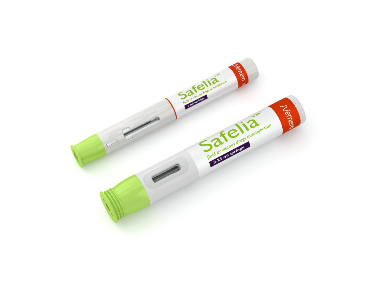
Figure 1: 1 mL and 2.25 mL versions of the Safelia™ autoinjector.
Considering patient adherence is an additional challenge. Less frequent injections, therefore larger volumes and more concentrated formulations, is a target for injection, devices which should also deliver with possibly less pain, less bruising and over a short delivery time.
Nemera’s new generation of two-step autoinjectors, Safelia™ (Figure 1), has been designed to ease the patient self-injection experience and to deliver a variety of drug products in glass syringes. These range from more fluid formulations to the most challenging drugs such as viscous, sustained-released, concentrated formulations, products for subcutaneous and intramuscular injection, and including larger volumes.
The Safelia™ autoinjector:
- Administers a large range of formulations and injection volumes; the platform can adapt by design to handle both fluid and highly viscous formulations, taking care specifically of biologics, sustain-released formulations and sheer-sensitive molecules, of up to 2.25 mL injection volumes
- Improves the patient experience, with the possibility to reduce needle gauge, reduce injection time, and slow down the needle penetration inside the body tissues, and gives the possibility of a delayed retraction for viscous injections especially.
DESIGN SPECIFICS

Figure 2: Comparative stress maps of the Safelia (top) and another marketed autoinjector (bottom).
The specificities of Nemera’s patented autoinjector design include the ability to handle high injection spring forces and deliver formulations in standard glass syringes. By design the coupling inside the autoinjector is not made around syringe’s flanges, a structural weak part of the syringe, but around the syringe shoulder (Figure 2). The spring release shock and the energy is absorbed by a rotating cam system and allows highly viscous injections as well as large-volume delivery. Risks of breakage are therefore reduced by design during triggering of the autoinjector but also during transportation, drop and handling.
THE SPRING FORCE & DRUG VISCOSITY PARADIGM
The mechanism of two-step autoinjectors, as their name indicates, involves two consecutive steps: cap removal and syringe emptying. Injecting a large volume (2 mL) of viscous formulations in a short time (10 seconds) using a thin needle requires greater force than smaller volumes over longer times. The consequence is that the higher the spring energy, the higher is the kinetic energy (E) delivered to the syringe at impact (just after needle insertion, and just before start of syringe emptying).
A high-energy spring will induce high syringe velocity during needle insertion. Thus, at the impact (just after needle insertion, and just before syringe emptying) the force on the syringe could lead to problems. Specifically, at impact, the syringe velocity reduction will produce high stress on specific syringe areas; resulting in syringe breakage in some cases.

Figure 3: Calculation of total force on syringe resulting from a spring force of 70 N.
Typically, using a spring force of 70 N could lead to 272 N applied on the glass syringe (air bubble is not considered in that calculation). This force can lead to glass syringe breakage.
Different methods can be used to reduce the risk of glass breakage:
- One way is to grip the syringe by the shoulders instead of the flanges as illustrated in Figure 4
- Another way is to use damping materials
- Finally another method is to reduce the impact force that can be transmitted to the syringe.
STUDY REPORT: REDUCTION OF INSERTION SPEED
Nemera recently conducted a study to investigate glass syringe fracture risk in autoinjectors by lowering the impact force that can be transmitted to the syringe. Stress analysis was used to demonstrate the effect of lower impact force on syringe stress level.
Method
Numerical simulation was performed using:
- Adams™ 2014 Multibody Dynamics Simulation. This software simulates all parts, movements and speeds. The out put of this simulation provides a full model.
- Finite element simulation with MSC Nastran™ 2014 Structural & Multi-discipline Simulation (Explicit transient).
This software simulates stresses between all parts at the calculated speed (Adams 2014).
Assumptions: deformable parts; transient dynamic simulation; and initial condition is the impact velocity given by the full model. The study compared two models: one with a straight cam guiding the syringe needle insertion and the other a model with a 45° cam, guiding the syringe needle insertion.
All other conditions were constant including: spring force; formulation viscosity; syringe size; needle gauge and length.
Results
As shown in Figure 5, the syringe speed was simulated during its shock with the device. Considering a spring 70 N, the maximum syringe speed was 5.4 m/s with the straight cam, and 4.6 m/s with the oriented cam. According to the configuration with the 45° cam, the syringe deceleration was smoother compared with the other configuration with a straight cam.
The deceleration distances can be estimated at 0.31 mm with the 45° cam compared with 0.34 mm with the straight cam (Figure 6). The distance leads to a reduced shock on the syringe.
The shock force on the syringe / syringe housing over the course of the auto-injection was simulated (Figure 7). As expected, maximum force on the syringe was lower (300 N) with the 45° orientated cam compared with the straight cam (350 N). Time to reach maximum force is also shorter with the straight cam. Similarly, as Figure 8 shows, the maximum stress on the syringe from the simulated auto-injection was lower with the 45° cam (30 MPa) compared with the straight cam (38 MPa).
Finally, the simulated stresses were mapped for each of the autoinjector designs, 45° cam and straight cam. Figure 9 shows that the highest stresses were all in the autoinjector shoulder, with higher stresses being generated from the simulated straight cam design, compared with lower stresses from the 45° cam design.
Study Conclusion
The tendency for larger injected volume with higher viscosity highlights the need to consider this risk at earliest stage in the development process. The results obtained during this study showed that by design, syringe speed at needle insertion can be reduced, as can the stress on the glass syringe, reducing the risk of syringe breakage.
CONCLUSION
The Safelia™ autoinjector combines design elements (summarised in Table 1) such as gripping the syringe by the shoulder rather than the flange, and a slower insertion time achieved through 45° orientation of the cam, which provide significant benefits in terms of patient comfort and safety (Figure 10).

Figure 4: Gripping syringe on the shoulders (right) instead of the flange (left) reduces overall stress.

Figure 5: Syringe velocity (m/s) over time during simulation auto-injections using a 45° orientated cam and a straight cam design.

Figure 6: Syringe displacement distances (mm) over the course of the simulated autoinjection.

Figure 7: Shock force (N) on the syringe / syringe housing during the simulated autoinjection.

Figure 8: Maximum stress (MPa) on the syringe from the simulated autoinjection with 45° cam compared with straight cam.

Figure 9: Simulated stress maps of the two autoinjector designs (top) straight cam and (bottom) 45° cam.

Figure 10: Benefits of the system for patient comfort and safety.
| Expected benefits | Standard autoinjector | Safelia | Safelia features |
| Creating possibilities for viscous injections with the same autoinjector platform as for standard glass syringes | ✘ | ✔ | Injects fluid and viscous drugs up to several hundred centipoise |
| Risk of syringe breakage eliminated Possibility of using all (or no) syringe flanges |
✘ | ✔ | No stress on syringe flanges |
| Enables increased spring force and use of small gauge needles (less patient pain) without risk of glass breakage | ✘ | ✔ | No stress on syringe flanges |
| Reduction of injection force peaks | ✘ | ✔ | Cam design to adjust injection speed |
| Drug is delivered at the right depth | ✘ | ✔ | Needle insertion disconnected from injection |
Table 1: Summary of Safelia benefits and features compared with standard autoinjector.

Figure 11: Nemera’s Innovation Centre at La Verpillière, near Lyon, France
Previous article
COMPANY SHOWCASE: CREDENCE MEDSYSTEMSNext article
THE DRIVE UNIT OF THE PATCH PUMP