
Citation: Behrenswerth A, Luther M-O, Hinsch B, “Crack Prevention & Process Controls in Prefillable Syringe Manufacturing”. ONdrugDelivery Magazine, Issue 55 (Feb 2015), pp 48-52.
Andrea Behrenswerth and Marc-Oliver Luther both of Gerresheimer Bünde, and Bernhard Hinsch of Hinsch Consulting (Hamburg, Germany), explain the most frequently encountered types of defects, their causes and specific approaches to process optimisation.
INTRODUCTION
In the production and processing of ready-to-fill syringes, a multitude of defects with varying levels of severity can occur. The spectrum extends from cracks that penetrate the glass body completely to superficial scratches. For efficient quality management it therefore makes sense to classify defects not only by patient risk but in a way that makes it possible to derive conclusions as to their cause.
The PDA Technical Report 43 defines a crack as break that penetrates the glass barrel completely.1 However, in light of the many different types of defects that can occur, this definition leaves a number of questions unanswered. For example, it is necessary to clarify how cracks which do not penetrate the glass barrel completely and those which do not lead to breakage or permeability (non-leaking cracks) are classified.
Various approaches are feasible for such a classification. From a quality perspective, it is a good idea to take the patient-risk associated with the impaired integrity of the glass barrel as a primary criterion. This results in a three-stage classification process leading to the identification of:
- Cracks: critical defects
- Checks: major defects
- Scratches: cosmetic (minor) defects.
Cracks result in a discontinuity in the glass matrix which impairs the glass barrel’s integrity. The substantial health risks to patients are potential leakage or microbiological contamination, so cracks are classified as a critical defect. If a crack is suspected, the defect must always be inspected. The methods used are described here below.
Checks are discontinuities in the glass matrix which do not impair the glass barrel’s integrity, even under mechanical or thermal stress. They are classed as major defects, but they do not pose any risk to patients. Scratches are superficial defects which can mean a loss of material, but do not cause discontinuity in the glass matrix and are therefore classified as cosmetic defects.
CLASSIFICATION OF DEFECTS BY LOCALISATION & CAUSE
If the classification of defects is to serve as the basis for the systematic optimisation of production processes, a differentiated view which is oriented on defect position and defect cause is useful. Syringe production involves a series of steps with interim quality inspections, the first of which is tube cutting.

Figure 1: Syringe manufacturing: forming the cone (centre) and finger flange (right).
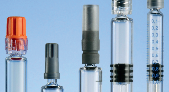
There are two forming processes in which first the syringe shoulder and tip, and then the finger flange are created (Figure 1). Next the syringe is optionally printed, annealed and, if the customer requests it, polished. Depending on the type of syringe, a needle is sometimes also glued into the hole of the syringe tip. The production of ready-to-fill (RTF) syringes involves a number of additional process steps in which the syringe is washed, siliconised and sterilised. Some are then fitted with a tip-cap, or a rigid or flexible needle shield (see Figure 2).

Figure 2: Components of an RTF syringe.
The customer-side processes also have to be taken into consideration. Unpacking and packing processes, filling, labelling and transportation exert mechanical loads and therefore can potentially cause defects in syringes which are supplied intact. It therefore makes sense to ensure that customer process management is tailored to the material of glass and for the customer to take recourse to the knowhow and support of the syringe manufacturer.
Defects can also be caused by factors outside the process chain. Each phase of production or processing is therefore associated with a specific range of potential defects which are typically located at a specific position on the syringe. For example, cracks typically occur on the finger flange, or on the syringe barrel originating from the finger flange or cone, and different types of cracks and damage can occur to the syringe barrel itself. Another problem is posed by so-called “cone cracks”, which aren’t cracks in the strictest sense, but lines or seams caused by the forming process.
Cracks on the Finger Flange

Figure 3: Examples of different types of cracks: a) on the finger flange, b) on the body, c) stress cracks, d) shell (or thermal) cracks, and e) impact cracks.
Cracks on the finger flange (Figure 3a) are classified as major defects because they do not impair the syringe’s integrity. They are predominantly located on the flat sides of the finger flange and are caused when the circular glass surface is cut in the production process. These cracks can occur if the glass is too cold or due to the temperature difference between the glass and the cutting tool being too great. The cause can also be mechanical when, for example, the cutting tool is too blunt, the overcut is not large enough or when cuttings collect in the cutting area. Accordingly, the cracks can be avoided by optimising the temperature setting, improving the tools and cutting parameters and by promptly suctioning off the cuttings.
Body Cracks
A study implemented by Gerresheimer Bünde revealed that 80% of body cracks (Figure 3b) are located on the cone side and 20% on the finger flange side of the syringe barrel. This is a critical defect because it can impair the syringe’s integrity, though assessments of body cracks have to be made on a case-by-case basis.
However, extensive tests have revealed that cracks of less than 1 mm in length do not cause leakage, even when the syringe is exposed to mechanical loads. Barrel cracks at the ends of the syringe are caused by tube cutting. The tubes are first scratched by a diamond blade. Afterwards the cut line is heated with a hydrogen burner and the tube is separated by application of a water nozzle. Cracks often occur when the nozzle is too wide or incorrectly positioned, so this defect rate can be considerably reduced by optimising the relevant parameters.
Stress Cracks
Stress cracks (Figure 3c) occur at the center of the syringe barrel. They can impair the syringe’s integrity, so they are classified as critical defects. Like body cracks, these are defects that have to be assessed on a caseby-case basis. Stress cracks occur due to inadequate annealing of the glass after the moulding processes, for example, due to a defect in the annealing oven. This defect’s rate of occurrence can be reduced by monitoring annealing in the production process and optimising the relevant parameters.
Shell Cracks (Thermal Cracks)
Shell cracks (Figure 3d) are also known as comma or thermal cracks. They, too, occur at the centre of the syringe barrel. Even though they are caused by thermal stress, shell cracks should not be confused with stress cracks because they are only superficial defects. They do not impair the syringe’s integrity, so they are merely classified as major defects. Shell cracks are caused by the temperature difference between the syringe barrel and the lining of the metal clamp that is used to handle the syringe being too great. They can thus be avoided by reducing the temperature difference or selecting a more suitable lining material.
Impact Cracks

Figure 4: An example of checks on the syringe barrel
Most of the above-described defects are caused by thermal stress. However, mechanical stress can also cause cracks on the syringe barrel (Figure 3e). These cracks can impair the syringe’s integrity, so they are classified as critical defects. Here, too, each crack has to be assessed on a case-by-case basis. They can be caused by a mechanical impact such as a knock, which can be avoided by gentle handling and transportation processes.
Checks on the Syringe Barrel
Checks on the syringe barrel (Figure 4) are caused in a similar way to impact cracks. They are a discontinuity in the glass matrix but do not impair the syringe’s integrity, so they are classified as major defects. Checks can be caused by mechanical damage during transportation or hard glassglass contact. Measures to avoid checks therefore include the optimisation of handling and transportation processes and the minimisation of contact between syringes.
Scratches on the Syringe Barrel

Figure 5: Scratches on the syringe barrel.
Scratches on the syringe barrel (Figure 5) only affect the surface and do not cause a discontinuity in the glass matrix. Therefore, they are classified as minor defects. The cause is glass-glass contact, which should be minimised in handling and transportation.
Cone Cracks
Spiral cracks with low fatigue strength called cone cracks can be found on the area where the cone meets the shoulder (Figure 6). These aren’t strictly cracks, but lines or seams, created in the forming process, which do not impair the syringe’s integrity. As a result, they are classified as a major defect. These cracks can be caused by an incorrect temperature profile in the forming process or if the forming roller presses the glass too hard as a result of the undercut diameter being too large, creating lines or seams. This defect can be considerably reduced by optimising the temperature profile.
AVOIDANCE OF CRACKS IN THE PRODUCTION PROCESS

Figure 6: Spiral cracks with low fatigue strength called cone cracks can be found on the area where the cone meets the shoulder.
By optimising the process parameters along the entire supply chain and using gentle handling technologies, glass defects in the production of ready-to-fill syringes can be systematically avoided.
Gerresheimer Bünde has implemented a pilot project and transferred the results to the other production lines. Customers in the biotech segment attach particular importance to low packaging-related reject rates because some of the pharmaceuticals they fill into the syringes are very expensive. The optimisation measures implemented by our mechanical engineering team extend from enhancing the precision of tube cutting, to optimising forming operations – particularly the cone forming process – and improved controls in the annealing process. Key overall project objectives were the reduction of temperature differences between the glass and the handling elements, and the reduction of mechanical stress during handling. Both the general avoidance of glass-glass contact and the selection of appropriate materials play an important role in this respect. For example pick-and-place technology, or the use of polyether ether ketone (PEEK) elements during syringe transportation ensure particularly gentle handling.
In-line production-quality inspections are performed with a third generation (G3) cosmetic camera system. The collaboration between the quality management and camera development teams is particularly important when selecting the defects to be identified. After forming the finger flange and before pressing, the syringe barrel is checked for cracks, checks and scratches, but also for bubbles, inclusions, airlines, glass particles and impurities. By rotating it on the vertical axis, it is possible to inspect the entire surface of the syringe barrel. Defects are identified on the basis of their specific grey scale contrast. The G3 system can theoretically detect defects as small as 0.0025 mm in length or with an area as small as 0.00625 mm2 . In practice, the system is currently used to detect defects with a length of 0.3 mm or longer or with an area of 0.1 mm2 .The shoulder, finger flange and transition areas can also be inspected for cosmetic defects.
CRACK CLASSIFICATION METHODS

Figure 7: Crack identification procedure flowchart.
Not all defects in a syringe penetrate the glass barrel leading to leakage or microbiological contamination. Thus it is necessary to differentiate between genuine cracks, which are critical defects, and checks or scratches, which are superficial and therefore only classified as major or minor defects. In this respect, the decisive issue is minimum strength under mechanical stress. Generally, all defects of less than 1 mm in length are leak-proof. There is a multistage inspection process for the systematic classification of defect type for syringes which are rejected in the visual inspection due to having defects of more than 1 mm in length (Figure 7).
Dimethylphthalate Test
The first stage of the classification process is to fill the syringe with dimethylphthalate (>99%), to wet the outer surface with dimethylphthalate and to clean it with a lint-free cloth. Dimethylphthalate has the same refraction index as glass. When viewed under an overhead light, scratches lose their typical shine when they are filled with the chemical. In contrast, cracks penetrate all the way through the glass. Since the chemical cannot fill the entire crack, it remains visible. In this classification process, all syringes with scratches can be identified.
Scratch Test
In the second stage of classification, the potential crack is tested to see whether it penetrates all the way through the glass. A syringe needle (27G with V-bevel) is scratched across the defect at a right angle. This procedure is repeated on the inside and outside at least five times. Any discontinuity in the glass matrix is perceived as slight resistance, because the needle gets caught on the ridge that is created. If the same effect occurs on the inside and outside, it is established that the crack penetrates all the way through the glass.
Ph Eur & DIN EN ISO Stress Tests
In the third stage of classification, tests are performed to see whether the defect becomes larger under thermal stress. There are two official procedures for this test. In the stress test pursuant to the European Pharmacopoeia Section 3.2.1A,2 the syringe is placed in a beaker and then put into an autoclave. The temperature is increased at a rate of 1°C/min to 121°C and maintained for 1 hr. Then it is cooled at a rate of 0.5°C/min to 100°C. In contrast, the stress test pursuant to DIN EN ISO 7459 includes temperature shocks such as occur in industrial processes.3 The syringe is placed in a water-filled beaker and heated up to 100°C. Then it is left in there for 5 min. The syringe is then dipped into a water bath at 20°C within one second and left there for 30 seconds. If the defect becomes larger during the stress test, it is classified as a crack.
Pressure Test
In the fourth and final stage of the classification process, the defect is tested for permeability. The syringe is sealed with a tip-cap or needle protector (RNS) and filled with a coloured solution (0.5% Triton X-100, 0.05% toluidine blue in water) to a level above the defect. Then the plunger head is inserted, any air pocket is eliminated and the plunger is screwed in. Pressure of 10 N is then exerted on the plunger and maintained for more than 30 seconds. Afterwards, the outside of the syringe is wiped in the area of the defect with a white cellulose cloth. If the blue solution is visible on the cloth, the defect leaks and is therefore classified as a crack. Otherwise, the defect does not penetrate through the glass (scratch test), remains stable under stress (stress test), is impermeable (pressure test) and therefore classified as a check.
Mechanical Test
An additional mechanical test can also be performed which involves the potential crack being exposed to mechanical stress from a die. The exerted force is gradually increased until the syringe breaks or a defined value is achieved. If the syringe breaks or the defect becomes larger under the defined load, it has a critical defect.
OUTLOOK
Processes and automated quality inspections with camera systems are today so advanced that the rate of cracks and cosmetic defects in supplied products is in the low ppm range. However, there is still potential for the optimisation of post-production processes at the customer’s site, particularly filling, visual inspection and packaging processes. Here, potential damage to the syringes can be avoided by reducing fall distances and shear forces. Collaboration between glass experts and the pharmaceutical industry early on in the production process and automation technology can contribute to the development of more efficient solutions. The same applies in the development of complex drug delivery devices containing syringes such as autoinjectors. Joint development operations will ensure that the syringe and injector’s dimensional tolerances and functional properties (siliconisation) can be optimally matched.
REFERENCES
- PDA Technical Report No 43, “Identification and Classification of Nonconformities in Molded and Tubular Glass Containers for Pharmaceutical Manufacturing”. Revised 2013 (TR 43).
- DIN EN ISO 7459:2004-05: “Behältnisse aus Glas – Beständigkeit gegen Abschrecken und Temperaturwechselbeständigkeit – Prüfverfahren (ISO 7459:2004)”. Deutsche Fassung EN ISO 7459:2004.
- European Pharmacopoeia (Ph Eur) 6th Edition, Basic edition, 2008 Vol. 1-3: 3.2.1, “Glass containers for pharmaceutical use”