


To Issue 150
Citation: Sampey P, “DFM & DFA: The Differences, Benefits and How to Implement Them.” ONdrugDelivery, Issue 150 (Jul 2023), pp 6–11.
Phil Sampey discusses the principles associated with design-for-manufacture and design-for-assembly methodologies as applied to drug delivery device design, giving an overview of what each involves and key areas of focus to ensure that the full benefits of these approaches can be realised.
Two concepts that frequently arise in current industry discussions are “DFM” and “DFA”. These concepts should be given consideration from the outset of a project through to after a product or device has been manufactured. So, what do they mean? What are the differences? How important are they? How can each one be correctly implemented in medical and drug delivery device development?
“When designing a component, both the desired function and design intent of the component should be considered whilst keeping the chosen manufacturing process in mind.”
DESIGN FOR MANUFACTURE
DFM stands for “design for manufacture”, the process of designing parts with a particular manufacturing process in mind. Designing parts for manufacture is a crucial aspect of device development.
DFM involves designing parts that are not only functional and meet the required specifications but that are also optimised for efficient and cost-effective production. The DFM process can be broken down into four areas:
- Chosen manufacturing process
- Part design
- Material selection
- The environment to which the parts will be exposed.
Consideration must be given to each of these areas. If just one area is neglected, it could lead to costly product failures further down the road.
The chosen manufacturing process and part design areas of DFM go hand in hand. When designing a component, both the desired function and design intent of the component should be considered whilst keeping the chosen manufacturing process in mind. The component should be designed to conform to the good manufacturing principles for the chosen manufacturing process. This will include considerations from the physical size and shape of a component to the specific geometry of individual features.
“Material data sheets are a fantastic resource, filled with useful information that can help with understanding material properties.”
For example, when designing for injection moulding, the part should be designed in a specific way, following the common design rules for injection moulding, such as using fillets and radii wherever possible to reduce stress concentrations, adding a split-line to the part, using draft angles on areas of the part geometry to aid the release from the tool and ensuring that there are no thick/thin sections or undercuts in the design. However, if it is decided that the part is to be computer numerical control (CNC) machined instead, then the design features of a CNC machined part would not necessarily need to incorporate most of these injection moulding design rules (Figure 1).
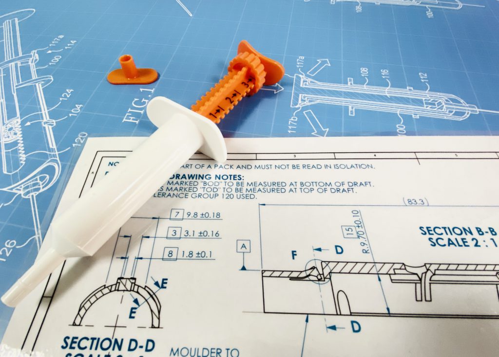
Figure 1: Part design and chosen manufacturing process go hand in hand, the considerations of one feed back into the other.
When it comes to material selection, choosing the final materials for the components of a device can have a big impact on the DFM considerations. Not only will the chosen manufacturing process play a part in selecting the right materials, but the specification and use case of the final product will help guide the selection of the best materials for the device. The following questions are just some key considerations for material selection:
- Will it need to withstand a load?
- Will there be any living hinges incorporated into the design?
- Will there be any snap-fits or clips?
- Does the chosen material need to be medical grade, sterilisation safe, food contact safe or hold a certain USP classification?
- Will the final device face have prolonged exposure to harsh chemicals, lipids or other biologicals?
In practice, the chemical resistance requirements of a device’s chosen final materials often take the top spot of importance when selecting final materials, trumping mechanical requirements. These are all important areas that can drive the material selection aspect of DFM and should be looked at holistically and in detail.
“Although DFA and DFM principles are often looked at as one combined subject, they are quite separate methodologies.”
Material data sheets are a fantastic resource, filled with useful information that can help with understanding material properties. Polymer datasheets provide detailed information about the physical, mechanical and chemical properties of a given polymer. This information can help determine whether the material is suitable for the intended application.
A section of polymer datasheets that is often overlooked is the thermal properties of the material. This section plays a huge part in ensuring that the final device can survive and operate in a particularly low- or high-temperature environment if required. The best design in the world won’t survive if the device’s features cannot perform within the specified operating temperatures of the application. Knowing the application and the environmental conditions that the device will be subjected to can be key to selecting the correct material.
DFM is an important part of any device development cycle. It should be considered early in the process to maximise cost and time savings. Appreciating and considering these four areas of the DFM process will ensure that a device is engineered and manufactured so that it performs to a high standard with robust, lasting performance. Addressing potential issues at the early stages of product development will help get it right the first time, or at least require less prototyping and fewer product iterations.
In conclusion, designing parts for manufacture is an essential aspect of product development. By understanding the manufacturing process, optimising for material properties, minimising complexity and considering tolerances and testing requirements, devices can be engineered so that they are not only functional but also optimised for efficient, cost-effective production.
DESIGN FOR ASSEMBLY
DFA stands for “design for assembly”, a process by which products and devices are designed with ease of assembly in mind. For example, if a product contains fewer parts, it will take less time to assemble, thereby reducing assembly time and costs. DFA is an essential aspect of engineering and manufacturing that plays a critical role in ensuring the successful and efficient assembly of complex devices. Properly designed components can reduce assembly time and cost, improve quality and reliability and enhance overall product performance.
Although DFA and DFM principles are often looked at as one combined subject, they are quite separate methodologies. DFA is the optimisation of the device and the assembly process, while DFM focuses on the manufacturing process and material selection. The aim of DFA is to make the assembly process easier, faster and more consistent to increase productivity. Some of the main principles of DFA to keep in mind are:
- Minimising part count
- Built-in fasteners
- Use of standard parts
- Part symmetry
- Poka-yoke assembly-specific design features.
Applying these principles throughout the design process will ensure the right path to achieving an efficient and successful device (Figure 2).

Figure 2: Following DFA principles can lead to reduced assembly time and costs for a device, as well as improved reliability and quality.
Minimising part count is an easy way to ensure that devices are quick to assemble. Well-designed devices with fewer parts usually end up being more durable, and easier to assemble and repair. Keeping the part count down will not only cut assembly times, and therefore assembly costs, but also prevent confusion during assembly and result in fewer assembly issues. However, be mindful that overly complex components might unnecessarily increase manufacturing costs.
It is highly beneficial to have a close relationship with the chosen manufacturer. Communication between designers and manufacturers is key to resolving complex part issues and helps to ensure that parts are designed efficiently and cost-effectively. Every manufacturer has their own way of doing things, so having a cohesive relationship with a chosen manufacturing partner is one of the biggest potential efficiency boosts for any design project.
Built-in fasteners should always be a consideration when designing efficient products. Although bolts, screws and rivets are relatively inexpensive, the installation of these fixings is very time-consuming. Built-in fasteners, such as snap-fits, speed up the assembly of the final device. Snap-fits don’t require any special production equipment and can make assembly quick and simple.
Using standard off-the-shelf parts instead of costly custom-manufactured parts, such as bushings and gears, will increase repeatability, save time during the assembly process and reduce assembly costs. Incorporating off-the-shelf parts into devices will also speed up the design process, as there are fewer custom parts to design and engineer.
Designing symmetric components is another way to ensure an efficient DFA methodology. This makes the assembly process easier for workers as it reduces the time spent trying to identify which way round similar looking components should be mounted.
Finally, incorporating assembly-specific design features into parts, such as physical obstructions to prevent components being fitted wrongly, or adding physical or graphical identifiers to parts that make them easier to identify and assemble, is one of the easiest ways to reduce assembly time. One of the simplest but most effective poka-yoke design features is the UK electrical plug and socket; the three-prong design for the plug and socket ensures that the plug can only be connected to the socket in the single correct orientation. Incorporating these poka-yoke design features into the component design will make sure devices can’t be assembled incorrectly and will avoid many potential issues down the line.
Designing parts for assembly requires a comprehensive understanding of the manufacturing process, product requirements and assembly considerations. By following the principles of DFA – standardisation, minimising part count, ease of assembly, modular design and material selection – designers can create parts that are optimised for assembly, which can result in improved product performance, reduced assembly time and cost and increased patient satisfaction.
A FINAL WORD
Hopefully this brief overview of the value that DFM and DFA principles have in device design has highlighted the importance of following these practices. Implementing these two methodologies can not only help reduce the time to market and costs of devices, but also be a guide to designing a more robust and effective device that can stand the test of time.