To Issue 188
Citation: Hassan S, “Designing a Wearable Drug Delivery Pump”, ONdrugDelivery, Issue 189 (Sep 2026), pp 48–51.
Dr Sammy Hassan delves into the measures required to ensure safe and reliable use of wearable drug delivery pumps, explaining the difficulties and benefits of incorporating such standards into a device.
Wearable drug delivery pumps are reshaping how therapy is delivered. By moving controlled, continuous and personalised dosing out of the clinic and onto the patient, wearable pumps can help to improve mobility, support home-based treatment, reduce hospital visits and enable precise regimens over extended periods.
However, a wearable pump is not a miniature pump strapped to the body. It is a safety-critical, medical, electrical system that must deliver the right dose, at the right rate, under shifting environmental, mechanical, electrical and user conditions. Over-infusion, under-infusion, occlusion, unintended activation, software malfunction, battery failure or a single mishandled interaction can all cause serious harm.
“SAFETY MUST BE A CORE DESIGN REQUIREMENT FROM DAY ONE RATHER THAN A LAYER ADDED JUST BEFORE SUBMISSION.”
Therefore, safety must be a core design requirement from day one rather than a layer added just before submission. A small group of standards frames this work: IEC 60601-1 sets the general requirements for basic safety and essential performance of medical electrical equipment; IEC 62304 defines the software lifecycle; IEC 60601-2-24 addresses infusion pumps and controllers specifically; and ISO 14971 provides the risk management process that ties them together.
THE OPPORTUNITY
The central opportunity is to bring essential treatments into everyday life. Ambulatory therapy lets patients receive medication while remaining mobile, which is valuable across chronic conditions, oncology, insulin delivery, pain management, hormone therapy and subcutaneous biologics.
Embedded electronics are what make accurate infusion possible. Sensors and closed-loop control support precise flow profiles, with bolus and basal delivery, programmable schedules and lockout periods tuned to the individual. Bluetooth, near-field communication or cellular links can add configuration, adherence tracking and remote diagnostics; designed well, they also give earlier warning of faults or misuse. As the device is worn by the patient, it must also be compact, light, discreet and intuitive (Figure 1). Meeting all these requirements at once pulls electronics, firmware, mechanical design and human factors into a single co-ordinated effort.
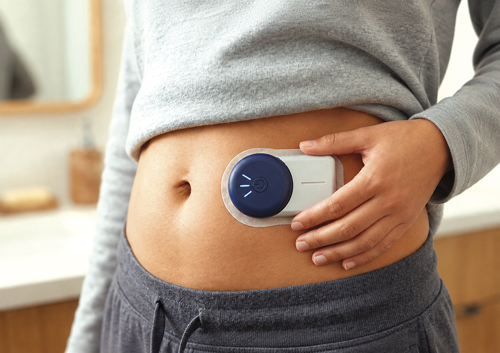
Figure 1: A person wearing an insulin pump.
SAFETY AS THE PRIMARY DESIGN DRIVER
The core challenge is in keeping the pump safe under normal use, foreseeable misuse and single-fault conditions – what IEC 60601 calls maintaining basic safety and essential performance. For an infusion device, essential performance typically means an accurate delivery rate, prevention of unintended delivery, occlusion detection, alarm generation and safe shutdown.
A safety-centred process starts with hazard identification and risk analysis under ISO 14971. Typical hazards for a wearable pump include:
- Over-delivery, under-delivery or a missed dose
- Downstream or upstream occlusion, or free flow
- Air ingress
- Liquid leakage
- Incorrect cartridge installation or patient set-up
- Accidental use of incorrect drug
- Battery depletion mid-therapy
- Software lock-up or timing failure
- Wireless interference or cybersecurity vulnerabilities
- Mechanical damage from impact, moisture or body movement.
Each hazard must be traced to a specific risk control – mechanical, electrical, software, procedural or, most often, several interlinked controls.
INTERLOCKS: A KEY SAFETY MECHANISM
An interlock prevents the device from entering a hazardous state unless defined safety conditions are met. In a pump these can be incorporated in hardware, software, mechanical design or the user workflow. They can include cartridge-presence detection, reservoir-door closure, cannula-insertion confirmation, priming and bolus lockouts, occlusion-triggered stops, battery undervoltage lockout and drug-container authentication (Figure 2).
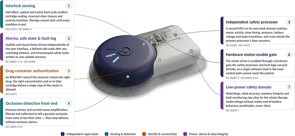
Figure 2: The safety measures that an insulin pump should contain.
“INTERLOCKS ARE NOT FEATURES FOR CONVENIENCE. THEY ARE RISK CONTROLS, WHICH MEANS THEY MUST BE SPECIFIED, VERIFIED, VALIDATED AND TRACEABLE TO THE HAZARDS THEY ADDRESS.”
A cartridge interlock, for instance, can block device operation until the drug cartridge is correctly seated, using a switch, Hall-effect sensor, optical sensor, radio frequency identification (RFID) tag or coded mechanical feature. A door interlock can prevent pumping while a reservoir or access panel is open; a priming interlock can stop delivery to the patient while the device is still priming.
Interlocks are not features for convenience. They are risk controls, which means that they must be specified, verified, validated and traceable to the hazards they address. IEC 62304 requires relevant software to be developed through a controlled lifecycle, with the software safety classification setting the level of rigour.
REDUNDANCY AND DUAL-PROCESSOR ARCHITECTURES
For high-risk delivery functions, a single microcontroller controlling the pump, reading sensors, managing alarms and supervising its own safety may not be enough. One software fault, timing error, memory corruption or lock-up could drive unsafe delivery.
“IF THE PRIMARY PROCESSOR MISBEHAVES, THE SAFETY PROCESSOR CAN DISABLE THE ACTUATOR, RAISE AN ALARM, FORCE A SAFE STATE AND LOG THE FAULT, CREATING AN INDEPENDENT LAYER OF SAFETY THAT DOES NOT DEPEND ON THE MAIN CONTROL PATH.”
A redundant architecture can mitigate single points of failure. A primary processor runs pump operation and the user interface (UI); an independent safety processor monitors the critical parameters – motor activity, delivery timing, pressure readings, battery voltage, watchdog signals and state transitions. If the primary processor misbehaves, the safety processor can disable the actuator, raise an alarm, force a safe state and log the fault, creating an independent layer of safety that does not depend on the main control path.
A robust dual-processor design typically includes:
- Independent watchdog monitoring between processors
- Separate clock sources for timing supervision
- Independent measurement of motor actuation or flow-related signals
- Hardware-controlled pump-enabled lines
- Safety-processor authority to disable delivery
- Cross-checking of dose counters and therapy state
- Non-volatile fault logging and a defined safe state after a fault.
“REDUNDANCY IS NOT FREE – A SECOND PROCESSOR ADDS COMMUNICATION, SYNCHRONISATION, POWER, VERIFICATION, PRINTED CIRCUIT BOARD AREA AND TEST BURDENS. IT SHOULD BE JUSTIFIED BY RISK ANALYSIS, NOT ADDED BY REFLEX.”
Redundancy is not free – a second processor adds communication, synchronisation, power, verification, printed circuit board area and test burdens. It should be justified by risk analysis, not added by reflex.
SOFTWARE SAFETY UNDER IEC 62304
Software sits at the centre of pump safety by providing dosing algorithms, motor actuation, alarms, user input, connectivity, logging and fault detection. IEC 62304 calls for a structured lifecycle: planning, architecture, detailed design, implementation, verification, integration testing, release, maintenance, configuration management and problem resolution.
Safety-related behaviours should be captured as explicit requirements, for example:
- Stop delivery when occlusion pressure exceeds the defined threshold
- Prevent bolus delivery during lockout periods
- Detect motor stall and enter a safe state
- Alarm before remaining battery capacity is insufficient for therapy
- Prevent therapy start if the cartridge is missing or misfitted
- Record safety-critical faults with timestamps
- Transition to a predefined safe state after watchdog timeout.
The architecture should isolate safety-critical functions within the device. Wireless and mobile-app features must never command delivery without passing through safety checks, and the therapy-control layer should be insulated from faults in the UI or communication layers.
IEC 60601 CONSIDERATIONS
As a medical electrical device, a wearable pump falls under IEC 60601-1 for protection against electrical and mechanical hazards, excessive temperature, abnormal operation and single faults. Three collateral standards matter especially here:
- IEC 60601-1-11 covers equipment used in the home environment, which is relevant because patients or carers, not clinicians, operate the device.
- IEC 60601-1-2 covers electromagnetic compatibility, which matters because a wearable device sits in the vicinity of phones, chargers, wireless networks and security systems all day.
- For infusion-specific requirements, IEC 60601-2-24 covers ambulatory, syringe, volumetric and controller pumps.
KEY ENGINEERING CHALLENGES
Dose Accuracy
Pump mechanism, motor control, reservoir design, tubing compliance, pressure variation, fluid viscosity, temperature and body position all influence delivery. The design needs calibration, verification and fault detection that keep dosing within acceptable limits.
Occlusion Detection
Low flow rates and small volumes make occlusions hard to catch. Pressure sensing, motor-current monitoring, flow estimation or displacement sensing may all be required – the real difficulty is detecting genuine occlusions quickly without flooding the user with false alarms.
Power Management
The device must be small and battery-powered, yet watchdogs, alarms, clock accuracy, memory integrity and fault monitoring must stay alive throughout delivery of the therapy. Low-power design must never quietly disable a safety function, and under-voltage behaviour must be predictable and safe.
Human Factors
Users may have limited training, impaired vision, reduced dexterity or anxiety about treatment. The device should minimise setup errors, give clear feedback and make unsafe actions difficult – through interlocks, guided workflows, alarms and physical keying.
Environmental Robustness
Sweat, moisture, vibration, impact, temperature swings and constant movement all act on a wearable device. Therefore, enclosure design, ingress protection, connector reliability, adhesive performance and mechanical retention all need deliberate attention.
Recommended Safety Architecture
A safety-focused wearable pump should layer its risk controls: a primary control processor, an independent safety processor, motor-driver-enabled control, cartridge and door interlocks, pressure sensing, motor feedback, battery monitoring, audible and visual alarms, non-volatile fault logging and a secure communication interface.
“WHEREVER POSSIBLE, HARDWARE INTERLOCKS AND INDEPENDENT MONITORING SHOULD BE INCORPORATED TO STOP A SINGLE FAULT FROM REACHING THE PATIENT.”
The primary processor handles scheduling, UI, connectivity and normal pump control. The safety processor independently checks that the primary processor is behaving and that critical outputs, such as the motor-enabled signal, pass through a safety gate that the safety processor or fault logic hardware can control. Crucially, safety should not rest on software alone. Wherever possible, hardware interlocks and independent monitoring should be incorporated to stop a single fault from reaching the patient.
CONCLUSION
Wearable pumps open real opportunities for patient-centric, remote and personalised care. However, because the device controls medication directly, safety must be designed into the architecture from the outset. IEC 60601 frames basic safety and essential performance, IEC 62304 governs the software lifecycle, IEC 60601-2-24 covers infusion specifics and ISO 14971 ties the risk picture together.
The safest designs do not lean on one perfect component or one flawless routine. They are layered systems in which foreseeable failures are detected, controlled and stopped before they reach the patient. Fundamentally, building those layers well is an electronics and embedded-systems problem as much as a clinical one.